I have wanted to get into this branch of antenna design for some time now but have always been put off by the endless input selections the programs require that may as well be written in Chinese. No chance of me ever understanding how to use it. I spotted this 4NEC2c antenna visualisation software for Linux whilst browsing the Amateur Radio software section in Synaptic. I thought, 'Why not download and install it and have a good play around with it'.
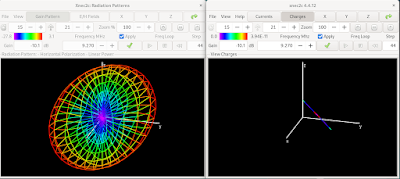
My first attempt was to model my 58 foot random wire antenna. Lots of the menus are still a mystery to me so I thought, '....just leave them at the default values'. I then moved on to the values that I did understand which is the X Y and Z geometry, the frequency range and input impedance. So here is my first model :-
(See update - this model appears to be incorrect)
Its interesting to note the gain values as you rotate the model. It seems like the highest gain, +5dB, is at 90 degrees to the wire at about 21MHz. I am still not sure it is entirely accurate but it looks convincing to me.
Update August 2024
Having recently switched back to using Windows, I am now using a different antenna modelling package. I entered the values for my 58 ft wire into this and the results were nothing like the output from 4NEC2c. My conclusion is that this model on this page was constructed incorrectly by myself. I do not blame the software. I am pretty sure that I have entered the wrong information. I have a better understanding of antenna modelling now and I have realised the error of my ways.
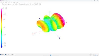
This is more like the actual model I should have arrived at:
This is the 7MHz model - not very good. Most of the energy is being radiated upwards (Cloud Warmer)
This is the 28MHz model. Much better with some forward radiation along the X axis.


No comments:
Post a Comment