Pages

Thursday, August 15, 2024

The 17-5 HF Vertical Antenna


This is the next project to be undertaken. Named the 17-5 because the top vertical element measures 17.5 feet in length. A short counterpoise wire of 3 feet completes the antenna when connected to the feed point via a 9:1 unun. The installation will be terminated with a 1:1 balun to deal with any common-mode current issues. I am reliably informed that the antenna will match up on 40m down to 10m, maybe even more.

I decided to model the antenna first to give me an idea of the radiation patterns. As you can see below, the take-off angle looks quite impressive - very similar to a ground plane antenna.


The far field plots show good gain figures at low angles with the antenna mounted at a height of 3m above ground. The 3D plot shows the highest energy radiation in pink / purple which is perfect for DX.


I have some fishing pole sections which I keep using and re-using for my antenna projects that can be utilised once again here. I slotted some sections together to give me a total of about 22 feet. I intend to feed the wires along the inside of the pole. The unun will be fixed at just over 3 feet from the bottom of the pole.

Completed Antenna


To test the antenna before erecting, I put it together and then stood it up in the washing line receptacle in the lawn. This is the temporary fixing of the 9:1 unun on the pole.


The antenna is 20.5 feet in total, which is still quite long.  A quick scan with the Nano-VNA showed reasonable SWR readings across the bands. So up it goes!


I decided to fit a waterproof box onto the pole to house the unun and partially cover the PL239 connection. Final position is above the garage on the gable end of the house, not ideal, but the most practical for my situation.

When permanently installed, I found that I could not get a decent match on 7 MHz and below. Also 18 and 28 MHz were a no-go. Proximity to buildings, metal brackets or other antennas? Who knows, probably all of the above. However, it did match up on 50 MHz which was a bonus, however, this may be outside of the efficient operating frequency of the unun, and consequently, I haven't made any contacts on this frequency yet with it.


Performance

It does work well, outperforming the 58ft wire sometimes. The long wire does work better on the lower frequencies though. I find antenna comparisons really difficult. Any tests you might perform are always against a backdrop of constantly changing conditions. I test using WSPR and comparing spot reports and also FT8 reports, but there are many variables to factor in. A good way I find to test the reception performance is to tune into a morse beacon and switch between your antennas to compare the S Meter readings. My wire antenna is horizontal while this is one is vertical. The long wire is in free space, while this one is quite enclosed between buildings. Despite all this I have made contacts in the USA and Brazil and across Europe, which is quite impressive. I will continue to try to improve the band coverage by firstly doubling the counterpoise to 6 feet. I have modelled this and it shows an improvement in SWR so let's see what happens. More to follow........


Monday, August 12, 2024

Simple Remote Antenna Switch

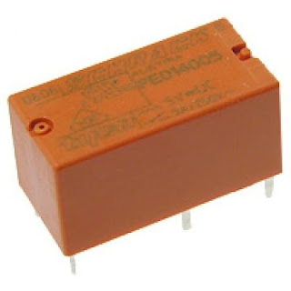
 I'm getting a bit bored with having to go to the airing cupboard to switch my antenna over. That's where the switch is located. My plan is to switch the three antennas I have installed by remote control. There are many ways to do this - just take a look online.  I intend to build a relay box to house the connections to the SO239s and Schrack miniature relays with contacts rated at 250VAC 8A. (see images below) 


Each antenna will have its own relay that will connect or disconnect as required. The coils of the relays will be operated by a 12 volt DC signal from a rotary switch, located in the shack. This arrangement also allows me to move all of the cables and switch box into the loft out of the way. Protection diodes were included along with some indication LEDs on the control box. The circuit diagram can be seen below:


Some designs use the normally closed contacts on the relays to ground the antennas not in use, while others just leave them open. I decided to go with non-grounded. I don't want to create a lightning magnet! I don't think there is any down-side to this. After all, my manual switch doesn't ground any outputs / inputs so it should be fine.

Testing:

I connected the Nano-VNA to the common input to the box and a dummy load to each of the outputs in turn. A sweep at different frequencies didn't show any adverse SWR readings compared to the manual switch. (in fact there is a slight increase in SWR with the manual switch and an identical increase with the relay box, so I'm guessing we're all good to go!) This is probably due to the extra connections being used. I think using coax to wire to the relays is a good idea here. I previously made a box, expecting the metal enclosure to provide adequate screening. Using coax makes for a reduced loss in the circuit.


I tested the unit live and made several contacts with no apparent problems. This is a project that has really been worth doing.


Tuesday, July 30, 2024

Why does anyone bother with Linux?

 The title says it all! I'm not on my own it would seem with my thoughts on this - just Google it. I installed it, gave it a fair crack of the whip, but in the end it had to go. I would have loved to stick with it. I get the idea that its an OS for developers and programmers, but so is any other OS. The difference is that other systems cater for both end-users and developers equally. Linux can be used like this because you can find some good complete package installers, but they are few and far between. Its like being given a luxury vehicle for free and then finding out that you can't get fuel for it. Trying to install and get something working is usually a nightmare! Pages and pages of code to type into the terminal and execute - this is after you have so called installed it in the first place. Most of the time it doesn't even work after this. You don't even know where the program has gone. But oh, the dedicated Linuxites are quick to tell you that you are doing it all wrong and you should try this or that. They don't use desktops or user interfaces, they run everything from the terminal, like this is a good thing. We are not all programmers or hackers. We just want an alternative OS to Windows so we can find and run applications on it. Linux can stay on the Raspberry Pi, best place for it! I capitulated in the end and this man went back to Windows. You need an application, you find it, you install it, and guess what? It works straight out the box! Don't get me wrong, Windows is not perfect by any stretch, but it is reliable for every day users. Ah well - rant over.

Monday, April 15, 2024

DXing In The 80's

During a bit of spring cleaning the other day, my wife found these old QSL cards dating back to the early 1980's. The one above was mine, AW26. I was immediately sent back to a time when CB and particularly DX was outlawed and it was a very clandestine operation to set up a radio station then. The QSL cards had to be sent by post because there was no internet. All very exciting! So here are a few more of them:-


This was from 1EP in Italy, handle "Hawkeye".


Kilo Sierra in Germany, handle "Meteor"


My wife also got in on the act using the callsign ESW26 and made this contact with "Anarchist" in Germany.


There were also a few from USA as you can see here:-


And also good old 'Blighty'


A snapshot in time. I really enjoyed finding these again. What would be very nice would be to get in contact with some of these people if they are still around.


4NEC2c Antenna Modelling Software


I have wanted to get into this branch of antenna design for some time now but have always been put off by the endless input selections the programs require that may as well be written in Chinese. No chance of me ever understanding how to use it. I spotted this 4NEC2c antenna visualisation software for Linux whilst browsing the Amateur Radio software section in Synaptic. I thought, 'Why not download and install it and have a good play around with it'. 

My first attempt was to model my 58 foot random wire antenna. Lots of the menus are still a mystery to me so I thought, '....just leave them at the default values'. I then moved on to the values that I did understand which is the X Y and Z geometry, the frequency range and input impedance. So here is my first model :-


Its interesting to note the gain values as you rotate the model. It seems like the highest gain, +5dB, is at 90 degrees to the wire at about 21MHz. I am still not sure it is entirely accurate but it looks convincing to me.

Update August 2024

Having recently switched back to using Windows, I am now using a different antenna modelling package. I entered the values for my 58 ft wire into this and the results were nothing like the output from 4NEC2c. My conclusion is that this model on this page was constructed incorrectly by myself. I do not blame the software. I am pretty sure that I have entered the wrong information. I have a better understanding of antenna modelling now and I have realised the error of my ways.

This is more like the actual model I should have arrived at:

This is the 7MHz model - not very good. Most of the energy is being radiated upwards (Cloud Warmer)

This is the 28MHz model. Much better with some forward radiation along the X axis.


Monday, March 25, 2024

Linux Home Station Upgrade


  For some time now I've been thinking of streamlining my setup. Using a large and ageing tower PC with keyboard and everything else takes up quite a lot of space in my small 'shack'. I recently acquired a 64 bit laptop. The tower PC was running Windows 10 and was getting slower with each update. In addition to this, I was getting spurious lock-ups and crashes mid contact which wasn't very good. It seemed like a good time to change over to a Linux operating system. Because the laptop was a 64 bit machine, I figured it would have no problem supporting the latest that Linux had to offer. Because I have had some experience with Debian, I decided to install the latest Debian 12.5. Everything went pretty well, apart from a few slip-ups with registering Dialout and TTY in groups. This is required for setting up any USB control functions. A little Googling sorted out my problems. I then moved on to installing the requisite apps to control my rig and to operate on FT4 / 8 with WSJT-X. I also installed Gridtracker as I had before on 'Windoze'. I can't believe how much faster the response is using this system now. Start-up and shut-down times have been reduced to mere seconds.

Since I had been using MSHV for my FT4 / 8 work, it took me a little while to familiarise myself with WSJT-X, but now everything is flying. Just a shame the propagation is so bad at the moment.

Monday, March 11, 2024

End Fed Random Wire Antenna


With the demise of the EFHW,  I decided to revert back to an EFRW. I don't know why they call it a random wire because there are set lengths that you use to get the best results. I tend to just refer to it as a long wire. This would only need a wire length of 58 feet, which makes for an easy fit in the garden. No need to divert around trees and the like. It is a straight run from the apex of the roof to the support pole at the bottom of the garden. However, the transformer would have to be reworked from a 49:1 to a 9:1 ratio (above diagram). That was easy enough to achieve. The secondary windings were reduced from 14 to 6, sticking with the 2 turns on the primary. I removed the capacitor also. Two type 240-43 ferrite rings were used as before. This is no longer a resonant antenna on any band, unlike the EFHW which is resonant due to utilisation of the harmonics. Running a check on the VNA confirmed that this would be promising with regard to SWR readings on all bands from 1.8MHz up to 28MHz. A higher SWR was observed on the 7MHz band and the 24MHz band of around 2.5:1 but nothing the ATU in the rig couldn't handle. I found that a 1m long counterpoise wire was sufficient to reduce the SWR readings even further and hopefully help with common mode current flow. A common mode choke was also employed on the coax close to the feed point. 

Conclusions:

The antenna performs as expected. Several good DX contacts were achieved - even on 10W. I rarely run above 30W anyway because I use mostly digital modes. I find this to be sufficient for contacts all over the world. These contacts include USA, Canada, Brazil, Suriname, Ukraine, China and most of the European countries. I have noticed though that the noise level may be higher. Not sure why this is. It doesn't appear to be on all frequencies. Could just be the normal noise level on a particular day. Conditions haven't been the best recently anyway. Overall, I feel more confident with this antenna than the 'fickle' EFHW. 


Sunday, March 10, 2024

EFHW Problems

I have recently been installing some reflective bubble-foil insulation in the loft and had to move my antenna so that all the wire is outside of the building. This meant losing a good few metres of wire as I am constrained with my available space. I had to run the wire vertically down the gable wall up to the level of the garage roof and then a horizontal run to the garden. This still wasn't enough space so I passed the wire around a tree at the top of the garden before heading for the support pole at the bottom of the garden. Major problems then ensued! I lost my decent SWR readings across all the bands except the 40m target band which was perfect. I then set about shortening the antenna and adding different counterpoises until I got something near workable. Still not very good. I think I have screwed everything up! What I can't understand is the near perfect match on 40m whilst the rest was a shambles!

So, decision made, I ordered a new 20m length of wire. I figured that if I start with a known quantity, I could work from there. I intend to 'steal' a few feet and put the supporting pole at the very extreme South East corner of the garden. (Hope the neighbours don't complain!)

Conclusions:

The new wire run did not improve things. This makes me think that the wire doesn't like the things it is coming into contact with, mainly, the wall. The wire is clipped to the wall vertically downwards. I am going to re-route this so it goes over the flat roof before going to the tree, keeping it mainly in free space. I am also going to lengthen the wire by about a metre or so. Looking at the VNA readings it looks like the wire is too short because the peaks and dips are low by about 1MHz on all bands, but I will do the re-route first and check again.

Update:

Nothing I was doing seemed to improve the situation. Although the EFHW still works, I have serious doubts about its efficiency and high SWR readings. My decision is to scrap the antenna altogether and start again with something different.

Wednesday, November 22, 2023

PL259 Versus BNC Plugs

 So it seems I may have found the problem I'm having with my VHF / UHF setup. I took some readings on HF frequencies and everything seems fine. After a little research, I discovered that a PL259 plug is apparently at it's limits at 100 MHz. A better choice for these bands would be the BNC or N type connectors. A quick reference to Wikipedia states:

Despite the name, the (PL259) UHF connector is rarely used in commercial applications for today's UHF frequencies, as the non-constant surge impedance creates measurable electrical signal reflections above 100 MHz.

Either this had slipped my mind or I never new about it! I have never liked the PL259 plug, but most radio equipment is manufactured to take these plugs. So it looks like I'll be doing some conversions. Caution is required because not all BNC plugs are the same. Some are only for CCTV applications and are probably not suitable. They need to be stated as 50 Ohms and for up to 3GHz usage. Also, if using the screw-in type, it is a good idea to check for continuity and short circuits on your coax afterwards. (I speak from experience here!) There are some handy converters on the market - see below.

PL259 to BNC converter.
BNC connection plug (50 Ohm Amphenol type or the screw fit).


Update:

 Well the connectors have been changed for the VHF / UHF side of things now and the analyser was connected up for testing again. To be honest, it hasn't made that much difference. I have only changed the connectors back to the antenna switch though. Maybe if all the connections were re-done it would improve things. Also, maybe some dedicated coax for VHF / UHF applications. That will be a work in progress. The system is useable as it is.


Tuesday, November 21, 2023

QFH Install

 So the rain stopped today and it was quite a nice day. The Quadri-Filar Helix Antenna has now been installed. I had to join the coax run indoors because it wasn't quite long enough to reach the antenna switch. I did this with two PL259 plugs and a back-to-back socket connector. (check for continuity and shorts) So now there is a mix of RG58 and RG8 Mini going to the antenna. Not ideal but it might suffice for what I'm doing just as long as the SWR is OK. Just hope there's not too much loss. A quick test with the analyser produced these results:


The image shows a sweep from 120 MHz to 150 MHz. All the markers are around an SWR of 2.


This image shows a sweep from 400 MHz to 500 MHz (100MHz sweep?) I'm not sure about this trace - it seems odd. All of the SWR readings are showing very low. Maybe I'm operating outside the parameters of the analyser (100MHz), It could also be that the antenna doesn't work on this band. It is, after all, designed for satellite reception on the 2m band. I'm not sure. I may have to delve a little deeper here to resolve it.

Testing the receive ability showed it to be working well on the 2m band. I tried the SWR meter on this band but it was reading quite high transmitting from my UV-5R handheld at 5 Watts. I don't know if the SWR meter is suitable for this frequency though. More checking required.


Saturday, November 18, 2023

A New Start

 This will be my new home from previously posting on my M7GBO blog. As mentioned before, I am currently working on improving my VHF/UHF setup and I am in the process of moving my QFH antenna.

The problem I have at the moment is the weather - it's atrocious! Just waiting for a dry spell because we've seen nothing but rain for a good few days. When erected it will make the working of satellites much better and also my general 2m coverage. If you would like to see what I got up to before this blog, check out https://M7GBO-UK.blogspot.com

The 17-5 HF Vertical Antenna

This is the next project to be undertaken. Named the 17-5 because the top vertical element measures 17.5 feet in length. A short counterpois...