Thursday, August 15, 2024
The 17-5 HF Vertical Antenna
Monday, August 12, 2024
Simple Remote Antenna Switch
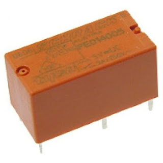
I'm getting a bit bored with having to go to the airing cupboard to switch my antenna over. That's where the switch is located. My plan is to switch the three antennas I have installed by remote control. There are many ways to do this - just take a look online. I intend to build a relay box to house the connections to the SO239s and Schrack miniature relays with contacts rated at 250VAC 8A. (see images below)
Each antenna will have its own relay that will connect or disconnect as required. The coils of the relays will be operated by a 12 volt DC signal from a rotary switch, located in the shack. This arrangement also allows me to move all of the cables and switch box into the loft out of the way. Protection diodes were included along with some indication LEDs on the control box. The circuit diagram can be seen below:
Some designs use the normally closed contacts on the relays to ground the antennas not in use, while others just leave them open. I decided to go with non-grounded. I don't want to create a lightning magnet! I don't think there is any down-side to this. After all, my manual switch doesn't ground any outputs / inputs so it should be fine.
(Update 02/08/2025. I decided to ground the antenna not in use connections on the relays. After weighing up the pros and cons, I did it mostly to get better isolation between antennas and not as static or lightning protection.)
Testing:
I connected the Nano-VNA to the common input to the box and a dummy load to each of the outputs in turn. A sweep at different frequencies didn't show any adverse SWR readings compared to the manual switch. (in fact there is a slight increase in SWR with the manual switch and an identical increase with the relay box, so I'm guessing we're all good to go!) This is probably due to the extra connections being used. I think using coax to wire to the relays is a good idea here. I previously made a box, expecting the metal enclosure to provide adequate screening. Using coax makes for a reduced loss in the circuit.
I tested the unit live and made several contacts with no apparent problems. This is a project that has really been worth doing.
10m and 20m Low Pass Filters
After a bad experience with a purchased low pass filter, I wanted to make my own for my WSPR transmitter for 10m and 20m bands. The ARRL hav...

-
With the demise of the EFHW, I decided to revert back to an EFRW. I don't know why they call it a random wire because there are set len...
-
I'm getting a bit bored with having to go to the airing cupboard to switch my antenna over. That's where the switch is located. My ...


